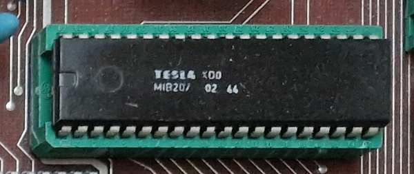
HP200

Gate array (semi-custom integrated circuit) implemented by ALS technology manufactured by Tesla Rožnov (or Piešťany, sources vary, same with technology that should be CMOS). According to the circuit datecode, it was produced around 1989.
From a topological point of view, the chip was divided into an edge part with edge buses Ucc and GND and with input and output converters that were evenly distributed around the entire perimeter of the chip.
The input transistor was divided into two-emitter units that could be connected to obtain gates with 2, 4, 6 and 8 inputs. The gates were designed with open collectors to create junction AND structures.
The gate matrix itself was located inside the area of the chip, defined by the input-output converters. A total of 240 gates were divided into a matrix of 6 x 40 gates. Each strip of 40 gates was fed from a separate voltage stabilizer, located at the end of the strip of gates. The belt of gates is surrounded on both sides by two rows of reserved spaces for the connection between the gates in the X axis in the first metallic level. In the center of the matrix, between the two rows of spaces for X connections, space is reserved for the main ground bus. Further connections between the gates can be made in the Y direction in the reserved spaces of the second metallic level. The typical delay of one internal gate was 2.5 ns, the typical delay of the input converter was 2.0 ns and the output converter was 6 ns. The external static parameters corresponded to those of TTL integrated circuits.
MIB circuits and MIC201 - 207 are pre-programmed gate arrays. According to this marking, only the size of the case and the operating temperature up to which this IO can be used can be known. On each circuit of the MIB/MIC201-207 series, there are four additional digits in addition to the production code. These four digits determine what kind of chip is inside and what this IO can do. I know the codes + function description from number 0202 to 0249.
MIB-plastic housing 0 to 70 degrees C.
MIC-ceramic housing -55 to 125 degrees C.
201 - 14 outlets
202 - 16 outlets
203 - 18 outlets
204 - 20 outlets
205 - 24 outlets
206 - 28 outlets
207 - 40 outlets
Semi-custom ICs based on HP 200
E.g. HP202, HP216, HP226 and HP227
- management of semiconductor memories
- bus control
- automation support
- MIB207/0231 CPU support logic circuit with I8088, contains WAIT insertion logic in microprocessor and CPU memory address decoder. Plastic case 40pin.
- MIB204/0217 8-bit bidirectional counter with data setting and comparison register with derived equivalence and 8-bit register. Three-state outputs. Plastic case 20pin.
Used e.g. for the parallel port in the TNS HC-16 computer.
A modified ISAN 1 printed circuit board design system was initially used to design the HP 200. The HW part of this system included an SM 4-20 processor, 256 KB RAM, CM 5400 cassette disk memory, CM 5300 magnetic tape memory, CM 7202 operator terminal, graphic CM 7405 display and Consul 2111 graphic mosaic printer.
Test System
The TADA 4 test system was intended for functional testing and for measuring static and dynamic parameters of digital integrated circuits with a max. the number of outputs is 40. The tester is controlled by a personal computer PP-06-2.