PIC Logix: Simple standalone logic analyzer
Features
- Minimalistic: Just two (2) important components + several capacitors/resistors and connectors
- Stand-alone, does not require PC - although it looks like running on a PC :)
- Displays output on VGA monitor or television (PAL and NTSC)
- Uses standard PS/2 keyboard
- 8 input signals
- up to 900kHz (can be extended to +- 2MHz)
- state analyzer (for JTAG at the moment, but anything is possible to implement)
- Open-source (GPL)
Design
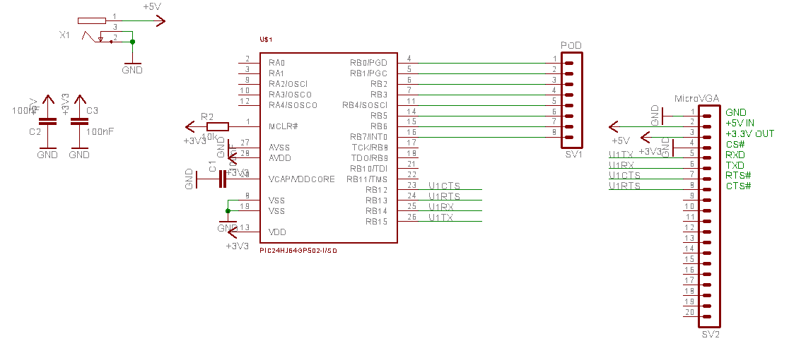
 PIC Logix has two major components. PIC24 or dsPIC33 for data capturing
(get chip with at least 4k of memory, I have used PIC24HJ64GP502) and
MicroVGA module for displaying
data and reading keyboard. Communication between these two parts
is over 1Mbit UART with CTS/RTS handshaking.
PIC Logix has two major components. PIC24 or dsPIC33 for data capturing
(get chip with at least 4k of memory, I have used PIC24HJ64GP502) and
MicroVGA module for displaying
data and reading keyboard. Communication between these two parts
is over 1Mbit UART with CTS/RTS handshaking.
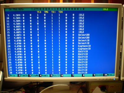
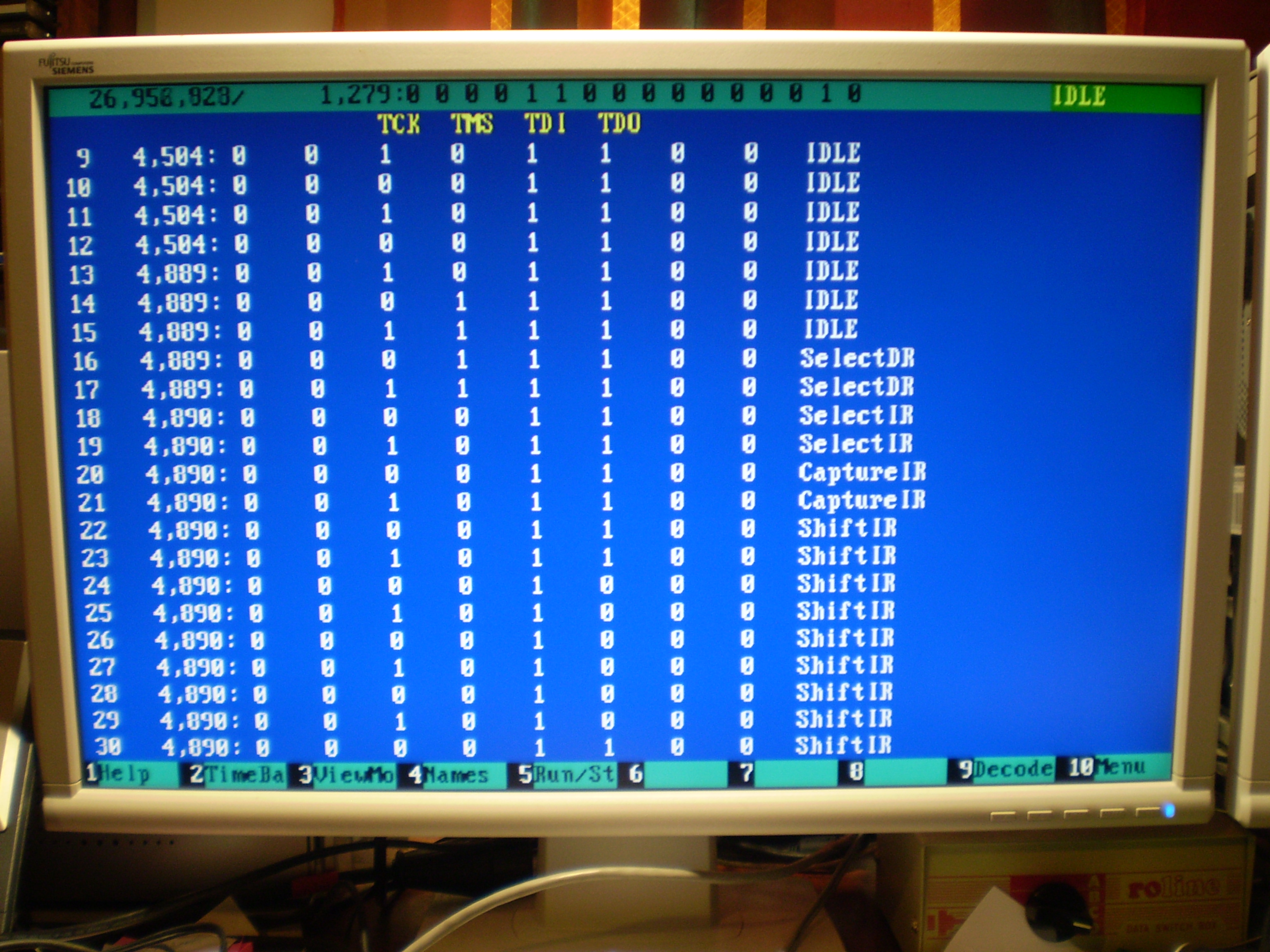
The logic analyzer captures using CN interrupt PORTB[0..7] states
and then displays them along with decoded state and timestamp on screen.
You can use arrow keys and PgUp/PgDn to navigate through listing in realtime.
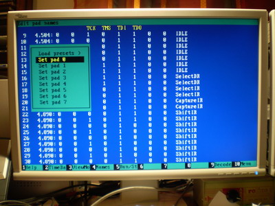
To start/stop capturing, press F5. To set pad names, use F4 key.
If you want to use JTAG state decoder, you have to connect TCK to RB2, TMS to RB3, TDI to RB4 and TDO to RB5. Press F9 to toggle display JTAG state information.
Please note that the whole project took about 3 hours, so it's far from being finished, but it's already usable. It worked for me, it may work for you too - but you will likely have to modify the code to match your needs and environment.
How to improve this project?
Speed can be increased by re-writing capturing code and use assembler. It would
also be good to allow omit timestamping and use CLK-triggered capturing. My
feeling is that it's possible to achieve +- 3 MHz logical analyzer.
State analysis for I2C/SPI/UART/CAN-BUS/J1850 as well as
byte decoding should be added.
Schematics
Getting components
dsPIC33 or PIC24HJ 40MIPS MCUs can be ordered from Microchip Direct.
MicroVGA can be ordered here, documentation is available on this page.
Download
piclogix.zip - source code & hex file
License
It's licensed under the terms of the GNU
General Public License.
Similar projects
Related links
Copyright (c) 2009 Martin Hinner,
martin.hinner.info

 PIC Logix has two major components. PIC24 or dsPIC33 for data capturing
(get chip with at least 4k of memory, I have used PIC24HJ64GP502) and
MicroVGA module for displaying
data and reading keyboard. Communication between these two parts
is over 1Mbit UART with CTS/RTS handshaking.
PIC Logix has two major components. PIC24 or dsPIC33 for data capturing
(get chip with at least 4k of memory, I have used PIC24HJ64GP502) and
MicroVGA module for displaying
data and reading keyboard. Communication between these two parts
is over 1Mbit UART with CTS/RTS handshaking.