SCART Pins and Voltage specs:
Sync / Composite Video In (Scart Pin 20): The sync pulses are active low signals
on the composite video line: 1.0 volts = White. 0.3 volts = Black, 0 volts = Sync
("blacker than black") So in RGB mode the line is normally 0.3v, pulsed to 0v for
the sync periods.
Red (Scart Pin 15), Green (Scart Pin 11), Blue (Scart Pin 7) Inputs:
0.7 volts = peak intensity of colour, 0 volts = lowest intensity of colour.
Note: I've found that my TV does weird things if there any voltages
above zero present on the RGB lines during the sync / back porch periods
(stuff like switching out of RGB scart mode, treating the colour present
during sync as a black reference) so it seems its necessary to inhibit
your RGB outputs during those times.
RGB mode select ("Blanking" Scart Pin 16): Some TV's let you toggle RGB mode via
the remote but to force it, put 1 to 3 volts on this pin. (5 volts via a 100 Ohm
resistor will set it at 2.1v due to the 75 Ohm load in the TV)
Note: All video (and control) signal lines see a 75 Ohm impedance at the TV end.
Video Ground: Scart pin 17.
Audio in (if required). Scart Pin 2 - left channel (or mono), Scart Pin 6 - right channel: 1 Volt
peak-peak signals (about 20K Ohms impedance)
Audio Ground: Scart pin 4.
SCART CONNECTOR PINOUT Table 1
|
Table 1 was the original and allows for composite video input/output,
RGB inputs and stereo audio. Table 2 was added to take S-video (S-VHS
and Hi-8) inputs. This made pin 15 chrominance and pin 20 luminance.
Many TV sets have 2 SCART sockets. One is usually loke table 1 and the
other like table 2, and pin 20 switchable from composite to S-Video
luminance.
The first can switch from a composite input to RGB input. The second
can switch from a composite input to an S-Video input, pin 20 being
either composite in or luminance in. Usually the second socket outputs
a selectable composite signal on pin 19.
|
 |
| Pin |
Signal |
Level |
Impedance |
| |
|
|
|
| 1 |
Audio Out Right |
0.5 V rms |
<1k ohm |
| 2 |
Audio In Right |
0.5 V rms |
>10k ohm |
| 3 |
Audio Out Left + Mono |
0.5 V rms |
<1k ohm |
| 4 |
Ground Audio |
|
|
| 5 |
RGB Ground Blue |
|
|
| 6 |
Audio In Left + Mono |
0.5 V rms |
>10k ohm |
| 7 |
RGB Blue In |
0.7 V |
75 ohm |
| 8 |
Audio/RGB switch / 16:9 |
High (9.5-12V) AVmode
Low (0-2V) TVmode |
>10kohm |
| 9 |
RGB Ground Green |
|
|
| 10 |
Comms Data 2 |
|
|
| 11 |
RGB Green In |
0.7 V |
75 ohm |
| 12 |
Comms Data 1 |
|
|
| 13 |
RGB Ground Red |
|
|
| 14 |
Ground Data |
|
|
| 15 |
RGB Red In / Chrominance |
0.7 V (Chrom.: 0.3 V burst) |
75 ohm |
| 16 |
Blanking Signal |
High (1-3V) RGB
Low (0-0.4V) Composite |
75 ohm |
| 17 |
Ground Composite Video |
|
|
| 18 |
Ground Blanking Signal |
|
|
| 19 |
Composite Video Out |
1V including sync |
75 ohm |
| 20 |
Composite Video In |
1V including sync |
75 ohm |
| 21 |
Ground/Shield (Chassis) |
|
|
SCART CONNECTOR PINOUT Table 2
| Pin |
Signal |
Level |
Impedance |
| |
|
|
|
| 1 |
Audio Out Right |
0.5 V rms |
<1k ohm |
| 2 |
Audio In Right |
0.5 V rms |
>10k ohm |
| 3 |
Audio Out Left + Mono |
0.5 V rms |
<1k ohm |
| 4 |
Ground Audio |
|
|
| 5 |
RGB Ground Blue |
|
|
| 6 |
Audio In Left + Mono |
0.5 V rms |
>10k ohm |
| 7 |
- |
- |
- |
| 8 |
Fuction Select |
High (9.5-12V) AVmode
Low (0-2V) TVmode |
>10kohm |
| 9 |
RGB Ground Green |
|
|
| 10 |
Comms Data 2 |
|
|
| 11 |
- |
- |
- |
| 12 |
Comms Data 1 |
|
|
| 13 |
Ground (chrominance) |
|
|
| 14 |
Ground Data |
|
|
| 15 |
Chrominance input |
0.3V |
75 ohm |
| 16 |
- |
- |
- |
| 17 |
Ground (luminance) |
|
|
| 18 |
- |
- |
- |
| 19 |
Video output (composite) |
1V including sync |
75 ohm |
| 20 |
Luminance input |
1V including sync |
75 ohm |
| 21 |
Ground/Shield (Chassis) |
|
|
| Cable between VCR and TV (Scart) |
| TV |
VCR |
| Audio Right Out |
1 |
2 |
Audio Right In |
| Audio Right In |
2 |
1 |
Audio Right Out |
| Audio Left Out |
3 |
6 |
Audio Left In |
| Audio Left In |
6 |
3 |
Audio Left Out |
| Audio Ground |
4 |
4 |
Audio Ground |
| Red |
15 |
15 |
Red |
| Red Ground |
13 |
13 |
Red Ground |
| Green |
11 |
11 |
Green |
| Green Ground |
9 |
9 |
Green Ground |
| Blue |
7 |
7 |
Blue |
| Blue Ground |
5 |
5 |
Blue Ground |
| Status / 16:9 |
8 |
8 |
Status / 16:9 |
| Reserved |
10 |
10 |
Reserved |
| Reserved |
12 |
12 |
Reserved |
| Fast Blanking Ground |
14 |
14 |
Fast Blanking Ground |
| Fast Blanking |
16 |
16 |
Fast Blanking |
| Video Out Ground |
17 |
18 |
Video In Ground |
| Video In Ground |
18 |
17 |
Video Out Ground |
| Video Out |
19 |
20 |
Video In |
| Video In |
20 |
19 |
Video Out |
| Ground |
21 |
21 |
Ground |
| S-Video Cable for Scart S-Video Input |
| S-Video Out |
TV, Scart (Input) |
| Luminance Out (Y) |
20 |
Luminance In |
| Chrominance Out (C) |
15 |
Chrominance In |
| GND |
4+17 |
GND |
| Audio Out L |
2 |
Audio In L |
| Audio Out R |
6 |
Audio In R |
| S-Video Connection Pinout |
| PIN |
DESCRIPTION |
Impedance |
Level |
| 1 |
GND |
Ground (Y) |
|
|
| 2 |
GND |
Ground (C) |
|
|
| 3 |
Y |
Intensity (Luminance) |
75 Ohms |
1V incl. Sync. |
| 4 |
C |
Color (Chrominance) |
75 Ohms |
0.3V Burst |
 |
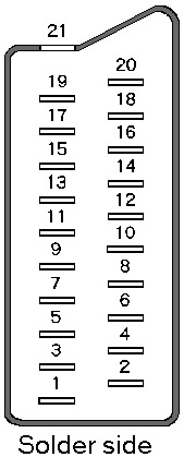
 View
to the solder side View
to the solder side
of the male connector |